


How can quick and easy measurements with the GS18 I be so accurate?

TheLeica GS18 Iis a versatile and easy to use GNSS rover that uses Visual Positioning technology to measure points remotely in images. The system integrates a GNSS sensor with an IMU and a camera. Due to its precisest sensor fusion, it is possible to measure inaccessible points in images right away in the field. I explained inQ&A on Visual Positioning and Leica GS18 Ihow the GS18 I captures and processes images. With this expert insight, we will take it one step further. I will describe some fundamentals of photogrammetry and take a closer look at the automated matching process that allows measuring of survey-grade points in images inLeica Captivate.
How is it possible to measure points by selecting only one point in an image?
捕获图像组后,立即吸引了GS18 I数据并计算每个图像的位置和方向。因此,用户可以选择一个图像,单击其中的一个点,按措施,然后“Voilà!” – 3D point coordinates have already been calculated in a global coordinate system. As you can see, the workflow of measuring points in images is effortless and straightforward. This is possible thanks to the highly precise and reliablepoint matching algorithm在Captivate上运行(通常称为AR跟踪)。
This seems relatively straightforward. But have you ever asked yourself how exactly the points are matched? To answer this question, I’ll first explain some fundamentals of photogrammetry.
Photogrammetry is the science of making measurements from images. The position of one point can be reconstructed from images that are positioned and oriented in a local coordinate system. The position of one object point can be defined by intersecting bundles of image rays, like in Figure 1.
Figure 1: Intersecting bundles of image rays

To be more specific, an image ray starts at a perspective centre of the camera, passes through the marked image point and goes to infinity, just like in Figure 2.
Figure 2: A perspective centre and an image ray

The object point we want to measure can be at any point along that image ray. To calculate the exact position of that point, at least two spatially separated image rays that intersect at one point are needed. These two rays must be defined by two different images. By increasing the number of image rays used for the reconstruction, the position accuracy will improve.
To define the direction of the image rays, users typically have to mark the point in each image manually. This is not needed when using images captured with the GS18 I. The following video nicely animates each step of the point matching algorithm, demonstrating how it automatically matches the marked point in the other captured images.
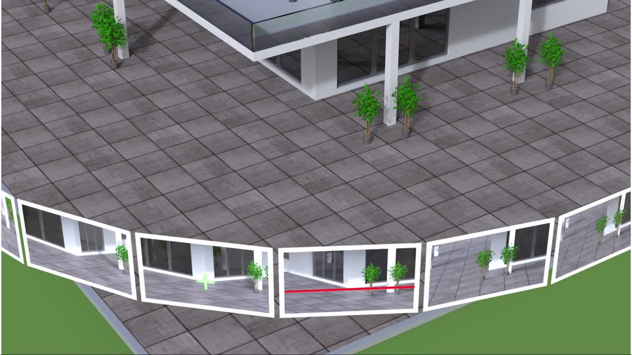
如动画所示,通过在选定的图像中标记一个点,将计算相应的图像射线。为了定义第二个图像射线的方向,必须在第二个图像中标记相同点。匹配算法的点通过将两个透视中心与基线连接起来会自动执行此操作。现在,使用基线和第一个图像射线,可以创建平面。这架飞机是所谓的epipolar plane, and it intersects the second image along the red line called the阴极线.
The epipolar line is crucial for the point matching algorithm because the point selected in the first image is located somewhere along the epipolar line in the second image. Therefore, the algorithm searches for the best match only along that line. First, Captivate defines atemplate matrix, a 19 x 19 matrix of greyscale pixels that surround the marked point of the first image. In the animation, the template matrix is framed by a green colour. In the second image, the algorithm detects in which segment of the epipolar line the point is located and makes a matrix scan only along this segment. By doing so, the processing time is reduced. During the scan, the algorithm extracts a 19 x 19-pixel matrix for each point along the selected part of the epipolar line.
In the next step, the algorithm searches for the best template match. Therefore, each of the matrices extracted from the second image are compared to the template matrix of the first image. This is done by calculating the correlations between the matrices. The extracted matrix with the highest correlation to the template is taken as the best match. Captivate then uses the surrounding pixels of this matrix to find the exact location of the point with sub-pixel accuracy. Captivate visualises this matched point with the blue symbol, and it appears in all images where the point was matched.
How smart is the point matching algorithm?
在开发匹配算法的点时,目的是创建一种像人类视觉意义一样擅长匹配的算法。但是,很明显,人造和人类的智力不能以完全相同的方式工作。例如,在许多用例中,匹配算法的点很容易匹配用户无法匹配的点。查看图3中的示例。
Figure 3: Point marked in one image (left) and matched in another image (right)

在图3的左屏幕上,图像中选择了管道上的一个点。在右屏幕上,同一点在图像组的另一个图像中自动匹配。一个GS18我用户问了一个很好的问题:“如何自动匹配其他图像中的标记点?这条管道沿线的每个点对我来说都是完全一样的,我看不到这条管道上可以在两个图像中手动匹配的一个唯一要点。那么,如果我不能,算法如何执行此操作?”
答案很简单。正如我之前解释, when a point is marked in one image, the matching algorithm first creates an epipolar line for each image. Then the algorithm searches along the epipolar line for the best match of the point. As shown in Figure 4, the epipolar line intersects the red line on the pipeline, and at the intersection point, the best match is found. And that is how it is easy for the algorithm to match the point in two images that the human eye could not distinguish.
Figure 4: Epipolar line

Sensor fusion, photogrammetry and cross-functional development to solve surveyors’ problems
视觉定位技术正在使用摄影测量原理进行远程测量。此外,传感器融合使GS18 I能够将GNSS和IMU数据与捕获的图像一起连接。摄影测量和传感器融合的独特组合简化了传统的摄影测量工作流程。此外,匹配算法的点加快了测量过程,甚至可以帮助用户测量无法在图像中手动匹配的点。这样,用户可以轻松地以测量级准确性测量图像中的点。不仅从现场图像中映射的映射不仅是现场的,而且在办公室中也继续使用相同的工作流程Leica Infinity.
在GNSS团队中,我们不断地推动界限开发解决测量师问题的新解决方案。通过开发一个简单的解决方案来衡量挑战点的传感器,我们希望扩展测量师在使用GNSS Rover测量时所具有的可能性。借助GS18 I,我们无疑证明,即使是最大的挑战也可以通过协同的团队合作来掌握。我们这样做是为了使我们的用户能够在使用GNSS Rover时以调查级准确性准确,可靠地执行远程测量。

Metka Majeric
Product Engineer
Leica Geosystems
To learn more about theLeica GS18 I, 请拜访:www.secondwindkites.com/GS18I

Contactez-nous Pour En Savoir Plus Sur Les Leica GS18
Contactez-nous Pour En Savoir Plus Sur Les Leica GS18, obtenir un devis ou une démonstration.